Mastodon

4.8.21

Bright priming

A break from building

Being very eager to paint this thing as accurately as I could manage, and because I just saw them in the shelves of Hobby Point when I went by, I had bought a couple of colourful primers that felt like a good match for the upcoming task. Red for what was going to be hull red, whiteish for those creamy chunks, that was the plan. While fooling with these I'd also finally start on those pieces that I had left to wait for priming *cough* road wheels *cough*

Round 1

I started with a bit of red primer (VSP 70642 Pure Red). After the first couple of puffs of the airbrush I felt a bit silly, as it was somewhat perverted to paint a tank bright red. I got over this sense of strangeness, as the coverage increased some more. When I was done with the first pass of the red parts, I switched to the lighter one (VSP 70627 Skeleton Bone) and went roughly over the combat compartment's white-to-be bits.


The engine I started painting upside down, purposefully, because I found it easier to hold onto from the top, while rotating and painting the submodel. That's why the aif filter cover was left for the next round.


I did the same with the fuel tanks and whoknowswhatpumps. They started to look like something now, even if I hadn't really done anything but giving some colour on them. Somehow that just gave some depth to the surfaces, in my opinion.


Rounds 2 and 3

During the next two priming rounds I did pretty much the same everywhere. First I finished painting those parts that I had previously only started on. Then I primed the already built parts of the tank's hull and proceeded to the tedious road wheels and other parts living nearby on the sprues.

This first photo showed how I had painted the insides of the top hull light, just as I did with the support beams that were going to be living behind the driver and the radio operator. I didn't do all the pieces now, as I wasn't sure if I had enough paint for a full set, and if I didn't, I had no idea when could I go buy some more.


Round 4

For this stage I painted the top of the hull, from the outside, prettily red (I bet someone had already done a bright red Panzer and added a yellow shield with an outline of a prancing horsey to the side), as well as the outer shell of the turret. What a setup this was going to be, indeed.


28.7.21

A bit of flooring

A small addition

Obediently following the instructions I built the inner floor bit to the rear end of the combat space. The vast majority of that piece consisted of a large circular hole, a place for the turret's floor to settle on to. While installing this into the tank itself I noticed that the tub was a bit too tight, and I couldn't safely bend it open enough for the piece to sit in perfectly anymore. That caused the left side (from the driver's POV) having an extra edge.

Now the engine department had the uninstalled bits (the motor, radiators/fans and the large fuel tanks) more or less sitting at their future sites. Dropping the top of the hull onto all this would be, should I say, interesting.


21.7.21

Backroom stuff

Support devices for the engine room

As mentioned in the previous post, at least one larger module was not installed to the engine, because it just could not be installed yet. What I could do instead was to assemble it for priming and basecoating.

Radiators and fans

The kitten's rear deck's fan complexes consisted of a couple of radiators and a fan sandwitched between them. Onto the outsides of these a couple of scoops that based on my quick guess were the air intakes while the fan blew the hot(ter) air out. Quickly built and neat-looking things, these.


More fuel tanks

The 145-litre tanks that were going to live between the radiators and the side hull were pretty quick to build. Both of them consisted of two large chunks and settled together decently. That rearmost tank's right edge had a hole that made me think if they were going to have fuel pipes attached or was I supposed to make one up myself. Hmmmm.

14.7.21

Maybach HL 230 P 30

A model in a model

Naturally the steely kitty had to have something inside to make it purr. This purrificator was like its own model, it was such a detailed and complex thing on its own. Before I started this project I had taken a look at what people had said about the kit, the engine was often mentioned on its own. Based on what I had read, I had decided to build and paint it separately, way before installing it inside the tank.

Central block

As usual, I had no proper understanding about motors or their specifics. The build began with that large block, that I knew to contain some cylinders, pistons and a crankshaft. So far so good, very clear stuff: attach these and trudge onward.


More little stuff almost flew onto the motor piece. From its front end (or rear end?) it apparently got attached to the tank's floor with some pretty simple-looking paws. At least they looked not-too-sturdy, but in this house we have always trusted in engineers.

This whoknowswhatsit that lived on top of the main block looked like a hidden face, a gas mask - wearing cartoon. In real life I guessed it had more to do with the valves and such would've lived, had this one not been a V12-engine. My next guess for this was that these also had something to do with mechanical timers or something. Interweb sources pointed towards a magneto, so that and some stuff related to air filtering most likely.


First V

To the end of the rightmost hand of the V was some kind of a container, that seemed to have some motor oil refilling caps and such, based on the look. With these little pipes the confusing and bothersome thing was that their installation angles weren't too clear to me.


Damn cool details, but was anyone going to see any of these when the installation was done? Most doubtful.


That was the first half of the upper end of the V-motor. I found the angle of the main piece a bit suspicious, but there was no clear sign of how it was exactly supposed to be, and the studs didn't give much if any haptic feedback again.

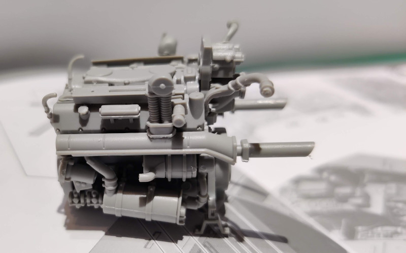
This next piece had presumably something to do with the exhaust system, being a large-diameter pipe attaching to the base of the motor. Unless that was something as odd as all of the exhaust piping that resided inside the tank, and it did look like that.


Second V

Being asymmetric the motor's second upper corner wasn't much quicker than the first one. Here a sickening amount of all kinds of weird lumps, ducts, pipes and narrower pipes were glued to live next to each other. Everything had to be set in place based on fancy 3d drawings and how the next step looked like in the instructions (or in the painting guide), and also by gut feeling. Personally I'd really appreciated clearer images and/or pieces that didn't make you guess if they were properly aligned.


The second exhaust pipe was funnily different from its sibling. With them installed even I started to figure out, which way it was supposed to be facing.


Below the exhaust pipe a bunch of interesting pieces found their homes. It'd been pretty neat to know what they were instead of having to ddg from who knows where. Any cylindrical bits were for moving liquids around, that much I could guess, but separating what was related to water and what to oil, that my eyes could not tell me.
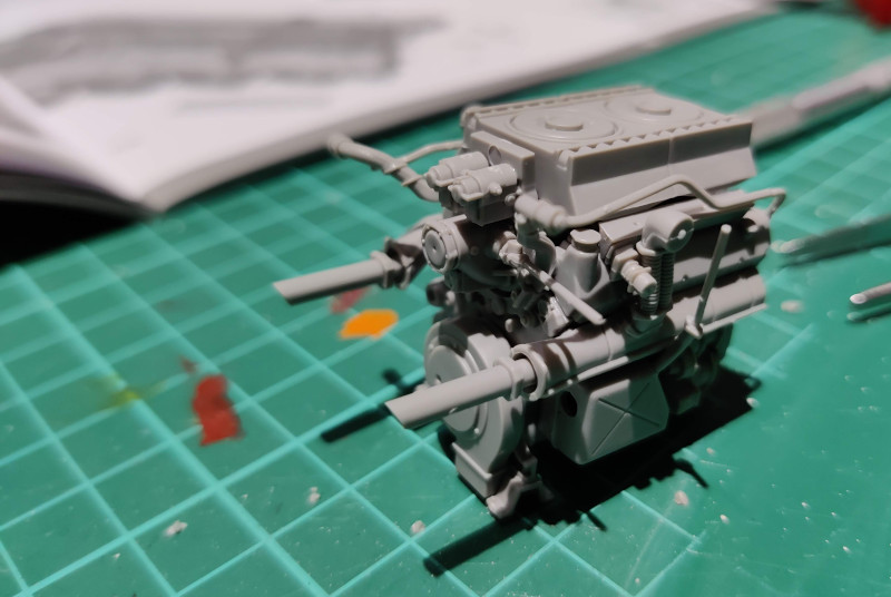

A readyish motor

After it had eaten a few evenings worth of tinkering time it was about done, as soon as the air filter's box was glued on. At this point only I could tell that the V angle was not correct but a bit too wide. Of course this piece of engineering was still missing some pipes, ducts and pumps, but those could not have been installed yet, because the motor wasn't in its place.


Behind its tank

While the last gluings were still curing I didn't even dream of smashing my motor inside its cubicle, but left it just behind the tank to pose a bit. Unbelievable, but true: it was indeed going to eat all that space and maybe even more. An astonishing monster of a motor.

7.7.21

An axle and some of its friends

Again the order of the instructions were a bit peculiar to me, of course I could've ignored that and just build these idler wheels when I built the drive sprockets. Or I could've just left them to wait for a priming and basecoating round, just like I intended to work with the road wheels. Apparently being consistent was someone else's method for working, not mine.


Transfer or power

Because the engine lived in the butt-end of the royal kitty and the gearbox complex in the front, something was clearly needed to make these setups communicate between each other. For that a couple of support setups were installed to the bottom of the tank (in the photo below, along the centerline) to attach the mechanical components onto.


The block assembled in the steps 15-16 was clearly something important related to this. I still had no idea about any of this particular subject, I just assumed it was some sort of a pre-gearbox thing, that for some reason was there, halfway between the gearbox and the engine.


The torque to this fresh piece of equipment was transferred by the first axle piece. This part lived just below where the turret's basked was going to be, so this could not be a random coincidence.


At this point I left the second axle to wait for a later stage, while whatever I had just installed was curing. Next I built a couple of walls to sandwich the motor. Before installing said motor. I found this slightly unnerving.

Onto both of these side walls I needed to install a strange-looking bit, seen below. Its function was not apparent from the pics, so I just assembled them, glued them in place and left poking as instructed.


These new walls didn't settle in as straight as their prussian heritage made me expect. Of course this flimsiness would be beneficial when installing the engine and its pipes, otherwise there'd be lots of breaking, and perhaps a couple of swear words filling the airways.


While these space dividers were setting, I glued the gearbox complex into the front floor of the tank, without forgetting the frontmost axle between the gearbox and the middle box. The positioning of these pieces were a bit off, I felt, as when the gearbox was accurately in the front, the rear end wasn't. Additionally this also affected the attachment of the axle too.


30.6.21

Zweiradienlenkgetriebe L801

Heavy hardware

Clearly the driver and radio operator had way too much footspace and too few tools. The solution to this problem was just behind the corner!

Control unit

Unlike the last Indiana Jones movie's tank, this jolly beast wasn't (only) controlled by pulling levers to brake the tracks, but via a steering wheel! The L801 steering device was a simple-looking two-piece module, that was glued onto a larger cylinder setup. The steering wheel didn't look too ergonomic to me, nor did was it a wheel, but that was just silly nitpicking.


Gearbox complex

As far as I understood the next setup consisted of the gear-housing (a 7-gear Zahnradfabrik AK 7-200) and a more blocky gearbox (OG 40 12 16B Schaltgetriebe). From now on, whatever all this should technically be called, will be referred to as "the gearbox" for simplicity.


FunkGerät 5

My King Tiger's radio setup consisted of a couple of boxes. Based on a couple of photos I found from the interwebs it should have a rack frame of some sort (painted white). Setting one up wouldn't be a problem, if one could count on the tank's upper part fitting on top of it. The larger box was a FuG 5, but I didn't recognize the smaller one as anything else - or a command unit's FuG 2 (unlikely, this didn't have the antennae required). This was the time I should've had a handful of very technical sourcebooks... in any case, whatever these were, they got installed on top of the gearbox housing.