Mastodon

29.7.20

More plumberiness

Wide ducts

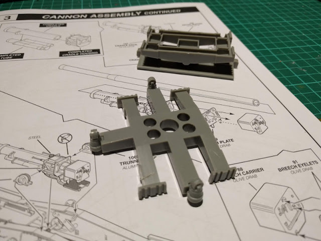
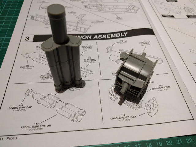
I continued assembling the busier end of the cannon. Below the barrel itself a three-cylinder recoil handling system. Next to it, in the photo below, was one of the core pieces of the gun's cradle.

Recoil system and cradle's core

With one of the tubes this looked like a small-scale Karl-Gerät's gun. The cannon barrel itself was still waiting to be installed, for at this point it would have been on the way more than anything else.

The recoil system and the cradle

I had to admit that I lost a shameful amount of time searching for the teethed piece that was responsible for the gun's elevation. The stepping plate seemed a bit flimsy at this point, but I thought I could strenghten it later, if needed.

Gun's cradle and such

These four rods I didn't clean up completely yet, as you could see in the photo. Fitting each four was a bit of a surprising struggle, but they got installed without much violence or threats of getting thrown into the trash.

The end parts of the gun


22.7.20

Interrupted plumbing

Results of the previous round

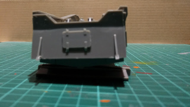
To begin with I checked what I had accomplished the last time. The carriage rotated neatly on its turntable, which was pretty cool. From the rear end I saw that the ground plate had ended slightly tilted, which in this case meant that if I was ever going to make some display terrain for it, the butt of the cannon had to be on a slight slope.

The rear plate, slightly tilted

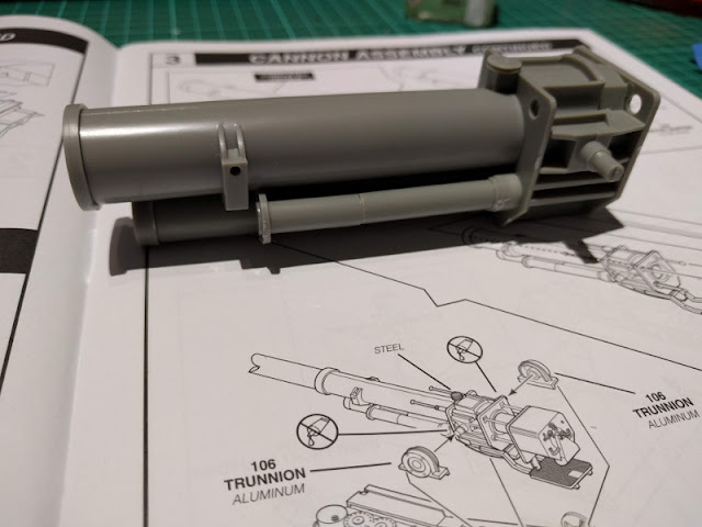
A barrel in three stages

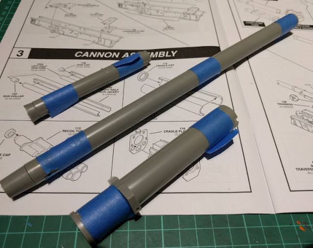
One of the key components of the atomic cannon, the barrel, consisted of a number of sections. I took this photo below when I had gotten the three first bits done and squeezed them tight with tape. Especially the middle tube wanted to split apart like an overripe banana.

Three cannon's barrel parts

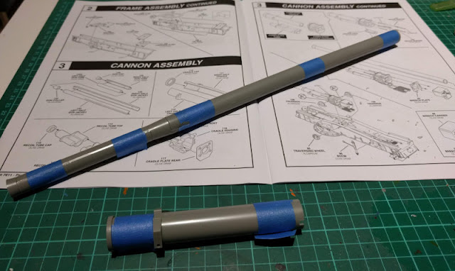
I had glued the two narrower components together and was about to proceed to the next step in the instructions, when I tipped my glue over. The remaining session time I spent on cleaning up.

That was a shame, for I had gotten to a pretty good pace, quickly.

Subcomponents of the cannon

15.7.20

Carriage work 2/2

A massive box trail

First things first: I wasn't 100% sure if this counted as a box trail but that term made more sense than the others - but if this was false, my apologies!

After a good amount of dry-fitting I glued the left half-block of the trail into the bits I had built the last time. I also remembered to add the missing axle-gear combo for the gun's elevation. The ways all these parts were all to be attached to weren't too clear in most of the cases, so I was being pretty damn paranoid before going for the glue.

Carriage progress

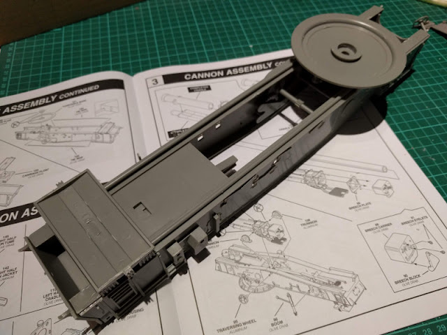
Onto the front and back ends of the bottom of the carriage a few pieces were added that, among other things, added structural integrity and helped keeping the thing in its proper shape. In the front of the next photo was the three-wheeled oddity that was used to rotate the cannon. And in the rear, guessing by the teethed bits, a part that was somehow tiltable and got installed to below the module that contained the hydraulic rammer.

Carriage's structural strenghteners

Some visible progress

The front of the carriage got a large-diameter (~2,7m) ground plate and the wheels that we saw in the previous pic were running on a track on top of it. This reminded me of the artillery in Suomenlinna for some reason. That setup in the rear of the carriage didn't get much more attention, my guess was that its tiltability was to allow for a less-than-billiards-table flatness of the firing position, meaning that it could be set on natural terrain in addition to some proving grounds.

Carriage assembled

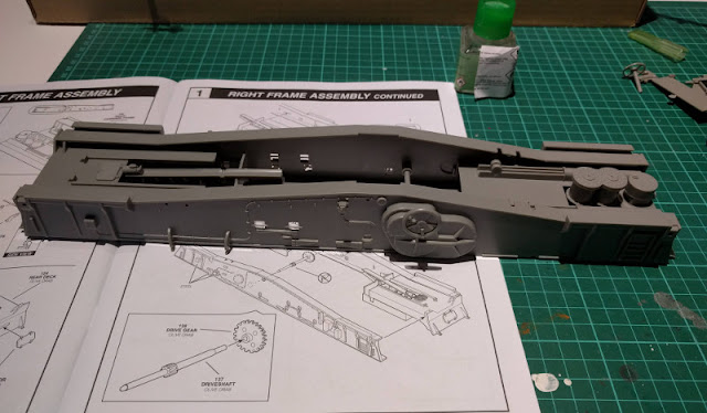
These long beams that ran along the length of the carriage didn't want to go in place decently, so I had to hack them a tiny bit. The one on the right side in the photo below needed much more tweaking than the other, first one. Still, nothing traumatic happened. Next I could start building the ordnance-delivery mechanism itself.

Carriage bottom details

8.7.20

Carriage work 1/2

The first evening

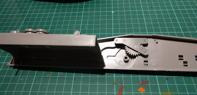
Being a nice boy I followed the instructions and started with the carriage. Perhaps I should've painted these pieces first, but that train went already. The first photo showed an interesting detail: working gears. I assumed that this meant that the cannon's elevation controls were actually working.

Parts of the gun's elevation mechanism

Behind the gun's breech block, in the end of the massive carriage a hydraulic rammer was to be built, for no one was going to ram the 272kg shells nor 385kg nuclear shells by hand. Nineteen long years later, I could almost hear the rattle of Giatsint-B's dragon's tongue when looking at this thing. Clearly time hasn't healed all wounds.

Loader parts

This was the subassembly that occupied the rear deck of the carriage. I didn't have the time to glue it into the righthand frame yet, or more accurately: I didn't want to glue it accidentally at an awful angle and realize it the next time I got to build. So I left it to wait for the next session when I was going to complete the frame itself.

Loader platform for the carriage

1.7.20

Project IV/20

M65 Atomic Annie

Again, after a good amount of pondering I chose the M-65 Atomic Cannon as my next project. According to the claims a weapon of this sort has been fired only one time, ever. Or at least its namesake special ordnance has been fired once, but one would assume that before that one shot at least one normal grenade has been propelled through the barrel.

The box

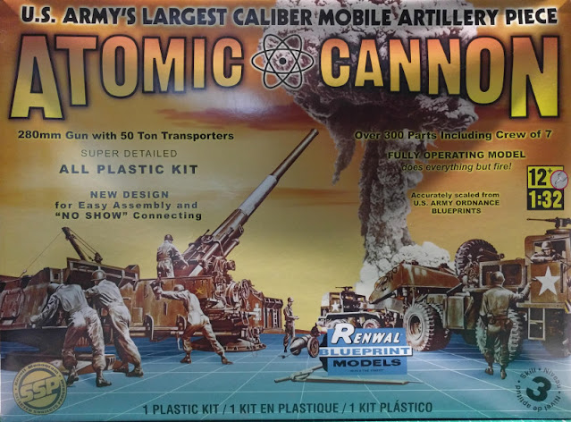
The Atomic Cannon's box was ridiculously large. Its cover art was somewhat different from what the typical ones have been during my years looking at them. This appeared to be Renwal's style before it got bought out by Revell, based on a quick image search.

Box front

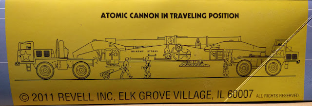
Box side, model in transport position

Papers, please

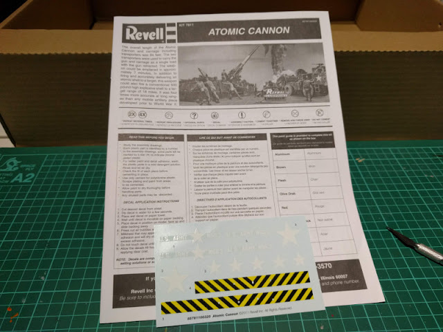
Decals were pretty simple, I thought I could even use the 'murican stars but the caution stripes would be so much better if just painted on the vehicles. Maybe this was partially my own disgust towards the decals as a medium, mixed in with my fear of those damn things going all spaghetti when applying them on anything. A huge effect has come from the fact that I have enjoyed painting and weathering a painted on detail has worked better than a brighter, higher-contrast decal.

Instructions and a decal sheet

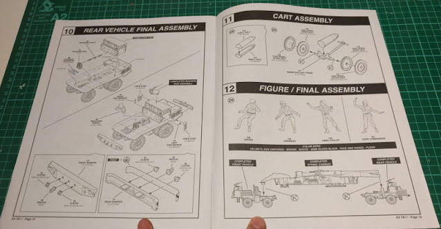
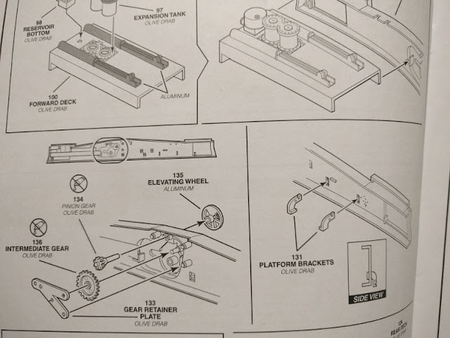
The instructions themselves were pretty nicely sectioned so I didn't need to guess what I was working on at any given point. In the second pic you could see an interesting detail that I couldn't recall seeing anywhere before: it named each subcomponent. This was exactly what I had wished to see in the airplanes, for example, and some more random projects than plain old tanks.

Instructions overview

Instructions details

Bits and pieces

There were, like the box said, a couple of hundred pieces to enjoy. To my great joy I found that a decent amount of said pieces were loose inside the box, torn out of their sprues over the years and kilometers. So an amount of the project time was going to be dedicated to finding out loose pieces. The numerous tire halves were at least pretty self-evident, but the rest...

Kit pieces overview: movers

The six-person crew consisted of single-piece humanoid males from the sixties. Maybe I'd paint them for a photo, but one couldn't do much dynamic things with these.

Kit pieces overview: wheels and crew

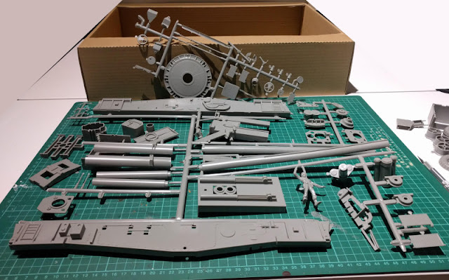
From this next set I had some difficulties in guessing which may have belonged to the carriage and which maybe to the vehicles, if the most obvious ones were ignored. These pieces were numbered, which was technically nice, but in practice reading the tiny numbers (where they hadn't fallen off) was a bit challenging sometimes - or my eyes were awful (also true).

Kit pieces overview: cannon base

The cannon's carriage was ridiculously large, but I guess it had to be, if the barrel's diameter was 280mm. At this point I was just guessing which set of sprues were prodiving which part of the build, more or less, so my comments may have also been totally off.
Kit pieces overview: cannon frame